สินค้า
EGF (245-550) kV
รายละเอียด
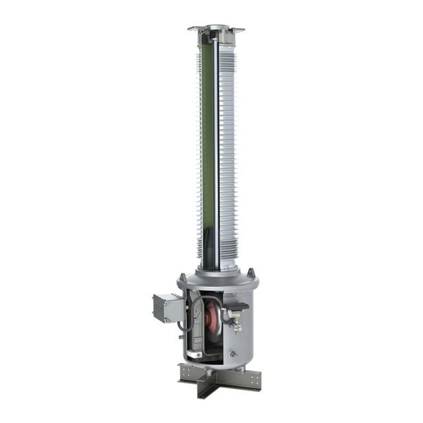
VOLTAGE TRANSFORMERS | OUTDOOR OPERATION
- SF6-gas insulated
- Pressure release by using a metal burst-disc
- Fine-graded foil bushing
- Gas density control
- Only silicone insulator available
Voltage transformers type EGF are used in high voltage substations within the 245-550 kV range. They transform high voltage into standardised, equivalent values for meters, measuring and protection devices.
GENERAL DESCRIPTION
Voltage transformers type EGF are used in high voltage substations within the 245-550 kV range. They transform high voltage into standardised, equivalent values for meters, measuring and protection devices.
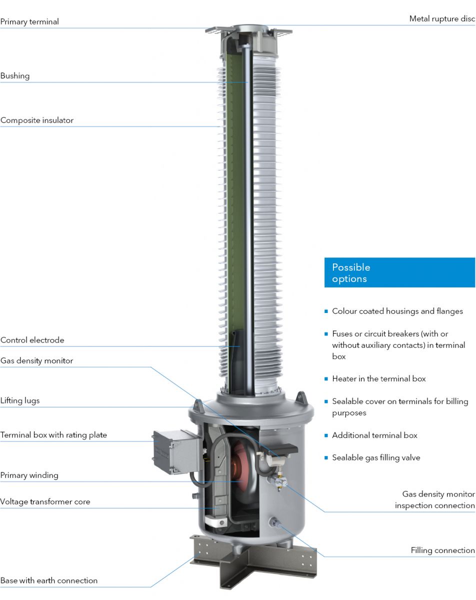
The active section of the voltage transformer is located in the pressureresistant foot housing. The iron core is on earth potential. The secondary windings are directly positioned on the iron core. The secondary windings are passed through an SF6 / air bushing into the terminal box. The high voltage connection is implemented via a short-circuit proof aluminium pipe.
The current distribution along the insulator is optimised by a special layout of the control electrode inside the silicone composite insulator.
The housing components consist of helium-tight, corrosion-resistant cast aluminium. All housing components under pressure are individually typetested according to applicable pressure vessel standards.
The SF6 gas density is monitored by a temperature-compensated gas density monitor with alarm contacts. The special design means the function of the gas density monitor can be checked without dismounting it.
A corrosion-resistant metal rupture disc, protected by a metal cover, is located at the top of the housing and ensures safe pressure relief in case of error.
The generously designed terminal box is equipped with a cover that opens sidewards.
Pure SF6 gas is used for ambient temperatures up to -40°C. The transformer is filled with a mixed gas for lower ambient temperatures up to -60°C.
Advantages of
inductive voltage transformers
- High operating safety through optimised current distribution in the field-controlled bushing
- Low weight and high creepage resistance through the use of composite insulators
- Special iron core provides protection against any ferro resonances
HIGHLIGHTS

Optimally protected
density monitor
- Precise function is ensured through temperature compensation down to -60°C.
- The density monitor is equipped with two alarm contacts to signal a pressure loss.
- The density monitor can be checked without dismounting it via a special test connection.
- A solid metal cover protects the density monitor against mechanical damage and direct sunlight.

Excellent protection
against moisture
- The inner side of the instrument transformer is protected against moisture by means of special sealing rings.
- All housings are designed with a drain-age area to protect the sealing surfaces of the housings against rain. This significantly reduces crevice corrosion.
- The housing elements are connected with special stainless steel screws. They are designed in such a way that no humidity can enter the screw hole.

Installation-friendly
terminal box
- The generously sized terminal box with a cover that can be opened sidewards, is secured with captive screws. It can accommodate terminal blocks, fuses, additional auxiliary contacts and sealable covers.
- The terminal box is equipped as standard with a blind flange. Cable glands can be installed on request.
- The terminal box has a protected ventilation aperture to prevent condensation.
DESIGN
TECHNICAL DATA

| Type EGF | 245 | 300 | 330 | 362 | 420 | 550 | |||
|---|---|---|---|---|---|---|---|---|---|
| Standard | IEC / IEEE | ||||||||
| Highest voltage for equipment | kV | 245 | 300 | 330 | 363 | 420 | 550 | ||
| Rated power-frequency withstand voltage | kV | 460 | 460 | 460 | 575 | 630 | 680 | ||
| Rated lightning impulse withstand voltage | kV | 1050 | 1050 | 1175 | 1175 | 1425 | 1550 | ||
| Frequency | Hz | 50 / 60 | |||||||
| Accuracy class | 0.1-3; 3P; 6P | ||||||||
| Rated thermal limiting output | VA | ≤ 3000 | |||||||
| Max. simultaneous burden (cl. 0.2) | VA | ≤ 300 | |||||||
| Max. number windings | 5 | ||||||||
| Nominal operating / transport overpressure (20°C) | bar | 4 / 0.5 | |||||||
| Type EGF | 245 | 300 | 330 | 362 | 420 | 550 | |||
| Height of unit* | A | mm | 3930 | 3930 | 4993 | 4993 | 5353 | 6183 | |
| Height to primary terminal* | B | mm | 3905 | 3905 | 4968 | 4968 | 5328 | 6153 | |
| Depth of unit including terminal box | C | mm | 1052 | 1052 | 1293 | 1293 | 1293 | 1293 | |
| Depth of unit base | D | mm | 742 | 742 | 1088 | 1088 | 1088 | 1088 | |
| Width of unit base | E | mm | 730 | 730 | 1075 | 1075 | 1075 | 1075 | |
| Distance between screw holes at base | F | mm | 600 | 600 | 900 | 900 | 900 | 900 | |
| Min. creepage distance* | mm | 6700 | 7500 | 8250 | 9050 | 10500 | 13759 | ||
| Gross weight, approx.* | kg | 670 | 670 | 805 | 805 | 820 | 850 | ||
| Gas weight, approx.* | kg | 21 | 21 | 34 | 34 | 36 | 39 | ||
*with standard composite silicone insulator, creepage distance 25 mm/kV